
1 Parameters of Battery Pack
|
Model of battery pack |
51.2V200AH
|
|
Nominal voltage |
51.2V
|
|
Rated capacity |
200AH |
|
Rated reserved energy |
10.24KWH |
|
Standard charging current |
0.2C |
|
Total charging cut-off voltage |
58.4 |
|
Cut-off voltage of charging monomer |
3.65V |
|
Standard discharging current |
0.2C |
|
Maximum continuous discharging current |
100A |
|
Cut-off voltage of discharging |
43.2V |
|
Charging temperature range |
0℃~45℃ |
|
Discharging temperature range |
-20℃~60℃ |
|
Single module Size(W×L×H) |
850*520*150mm(excluding pylons)
|
|
Weight 1PCS |
Single module 100kg±5% |
1-2 Technical Parameters of Battery Management System (BMS)
|
Items |
Details |
Standard |
|
Cell overcharge protection
|
Overcharge detection voltage |
3.65V |
|
Overcharge detection delay time |
Typical:1.0s |
|
|
Overcharge release voltage |
3.40V |
|
|
Cell over-discharge protection
|
Over-discharge detection voltag |
2.70V |
|
Over-discharge detection delay time |
Typical:1.0s |
|
|
Over-discharge release voltage |
2.90±V or charge release |
|
|
Over-current protection |
discharge Over-current protection current1 |
110A |
|
discharge Over-current detection delay time 1 |
15S |
|
|
discharge Over-current protection current 2 |
120A |
|
|
discharge Over-current detection delay time 2
|
≤500ms |
|
|
Charge OC protection current |
110A
|
|
|
Short protection |
Short protection current |
412A
|
|
Protection condition |
External load short circuit |
|
|
Detection delay time |
≤500us |
|
|
Protection release condition |
Charge release or reset |
|
|
Temperature(T) protection |
Charge high T protection |
55±5℃ |
|
Charge high T recover |
50±5℃ |
|
|
Discharge high protection |
60±5℃ |
|
|
Discharge high T recover |
60±5℃ |
|
|
Charge low T protection |
-5±5℃ |
|
|
Charge low T recover |
0±5℃ |
|
|
Discharge low T protection |
-20±5℃ |
|
|
Discharge low T recover |
-10±5℃ |
|
|
Balance |
Balance threshold voltage |
3.50V |
|
Communication |
It has RS485 and CAN standard communication interface, it can real-time monitoring the capacity of battery bank, the voltage, current, environment temperature, and charging/discharging current. |
|
|
Alarm |
It has over-temperature, over charge, under-voltage, over-current, short circuit alarmFunction. |
|
|
Items |
Details |
Standard |
|
Cell overcharge protection
|
Overcharge detection voltage |
3.65V |
|
Overcharge detection delay time |
Typical:1.0s |
|
|
Overcharge release voltage |
3.40V |
|
|
Cell over-discharge protection
|
Over-discharge detection voltag |
2.70V |
|
Over-discharge detection delay time |
Typical:1.0s |
|
|
Over-discharge release voltage |
2.90±V or charge release |
|
|
Over-current protection |
discharge Over-current protection current1 |
110A |
|
discharge Over-current detection delay time 1 |
15S |
|
|
discharge Over-current protection current 2 |
120A |
|
|
discharge Over-current detection delay time 2
|
≤500ms |
|
|
3-2 Wall mounted battery mount 壁挂电池安装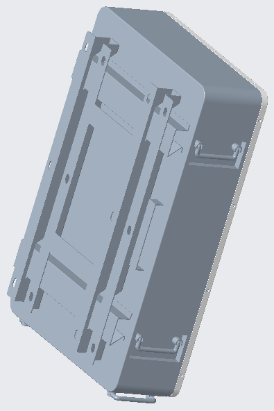 Charge OC protection current Charge OC protection current
|
110A
|
|
|
Short protection |
Short protection current |
412A
|
|
Protection condition |
External load short circuit |
|
|
Detection delay time |
≤500us |
|
|
Protection release condition |
Charge release or reset |
|
|
Temperature(T) protection |
Charge high T protection |
55±5℃ |
|
Charge high T recover |
50±5℃ |
|
|
Discharge high T protection |
60±5℃ |
|
|
Discharge high T recover |
60±5℃ |
|
|
Charge low T protection |
-5±5℃ |
|
|
Charge low T recover |
0±5℃ |
|
|
Discharge low T protection |
-20±5℃ |
|
|
Discharge low T recover |
-10±5℃ |
|
|
Balance |
Balance threshold voltage |
3.50V |
|
Communication |
It has RS485 and CAN standard communication interface, it can real-time monitoring the capacity of battery bank, the voltage, current, environment temperature, and charging/discharging current. |
|
|
Alarm |
It has over-temperature, over charge, under-voltage, over-current, short circuit alarmFunction. |
|
Panel operation instructions
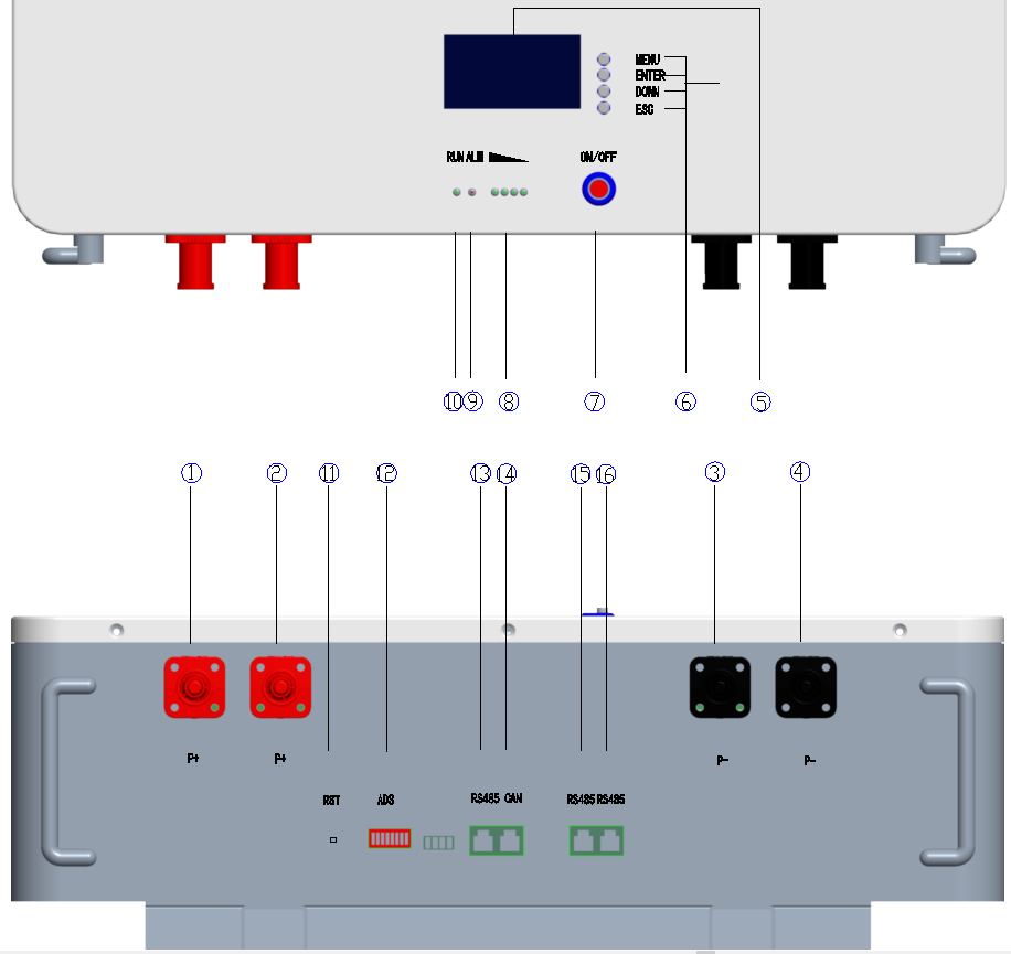
|
No. |
Description |
Silk-screen |
Remark |
|
1 |
Battery + |
P+/P+ |
Positive terminal |
|
2 |
Battery + |
P+/P+ |
Positive terminal |
|
3 |
Battery - |
P-/P- |
Negative terminal |
|
4 |
Battery - |
P-/P- |
Negative terminal |
|
5 |
LCD |
|
Display screen |
|
6 |
LCD KEY |
|
|
|
7 |
Output ON/OFF |
OFF/ON |
Switch breaker |
|
8 |
Electricity volume indicator |
LED |
Display the battery's capacity |
|
9 |
ALM alarm indicator light blinking |
ALM |
Red- trouble-light on |
|
10 |
Run indicator light |
RUN |
Display state information |
|
11 |
On/OFF button |
RST |
Reset key |
|
12 |
ADS Dialer |
ADS |
Display connection address |
|
13 |
RS485A port |
RS485A |
RS-485connection port-A RS485 |
|
14 |
CAN port |
CAN |
CAN communication port |
|
15 |
RS485B port |
RS485B |
RS-485connection port-B RS485 |
|
16 |
RS485B port |
RS485B |
RS-485connection port-B RS485 |
3-2 Wall mounted battery mount
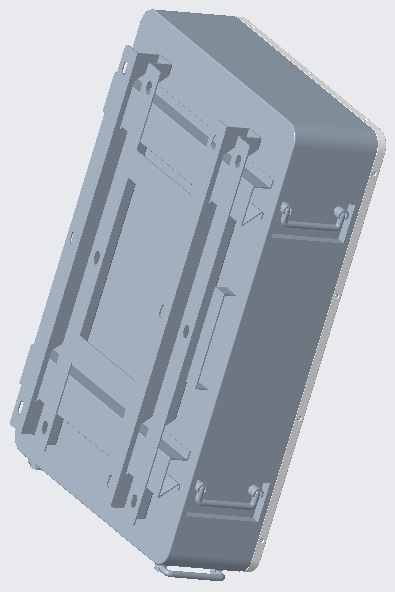
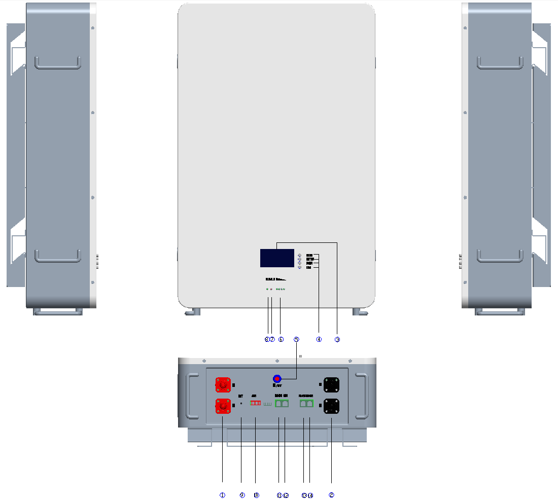


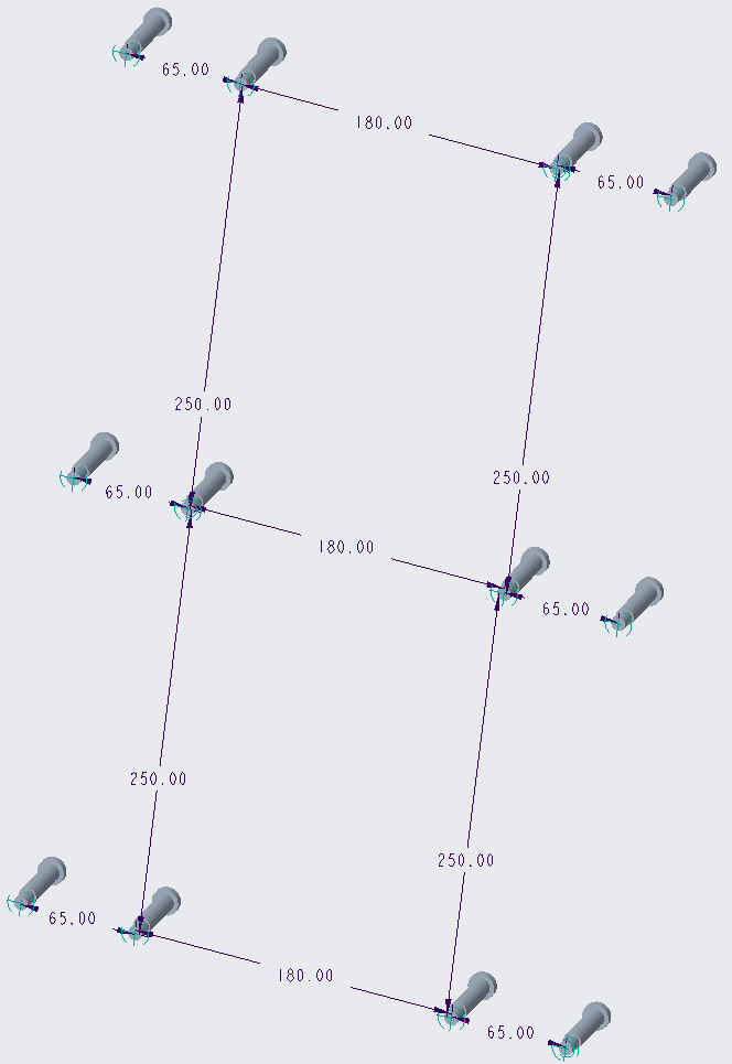
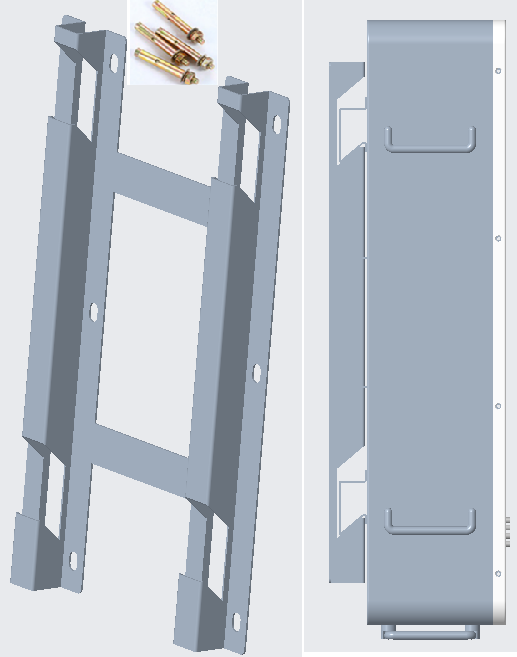
Wall-mounted battery installation schematic diagram, the specific situation according to the actual order requirements operation
Battery Management System
Performance Curves


